
Electrical Subsystem
2026 Electrical Team
Anna Joy Aylward Burgess, Yau Hong Chau, Thomas Coady, Tinhinane Ramdani, Julian Ambrose, Alec Boudreau, Alan Brotherton, Rachel Bunsick, Awab Choudhury, Leila Daoud, Masa El-Soufi, Justin Ferreira, Jean Flichy, Amélie Labeau, Matt Levasseur, Dorothy Ma, Benjamin Nysetvold, Amir Saadati, Céline Shao, Veronika Slobodyan, Oscar Tesniere, Mia Valderrama-Lopez, Jason Wang, Stanley Zhang
SYSTEM DESIGN
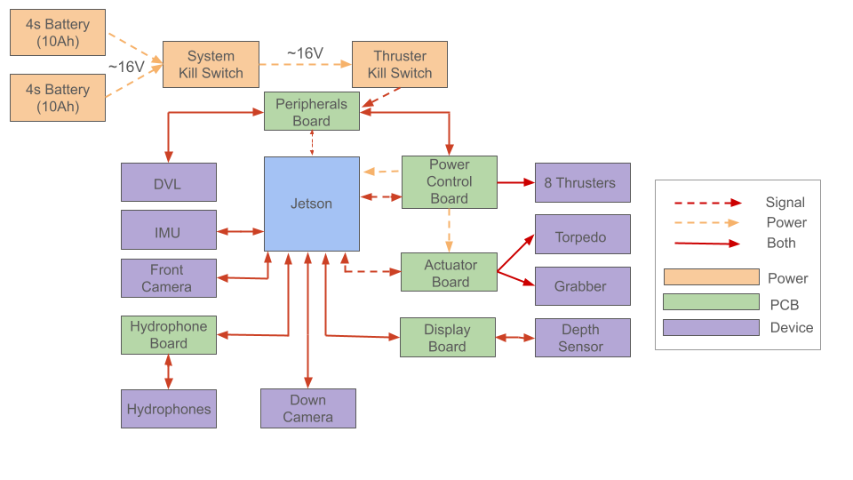
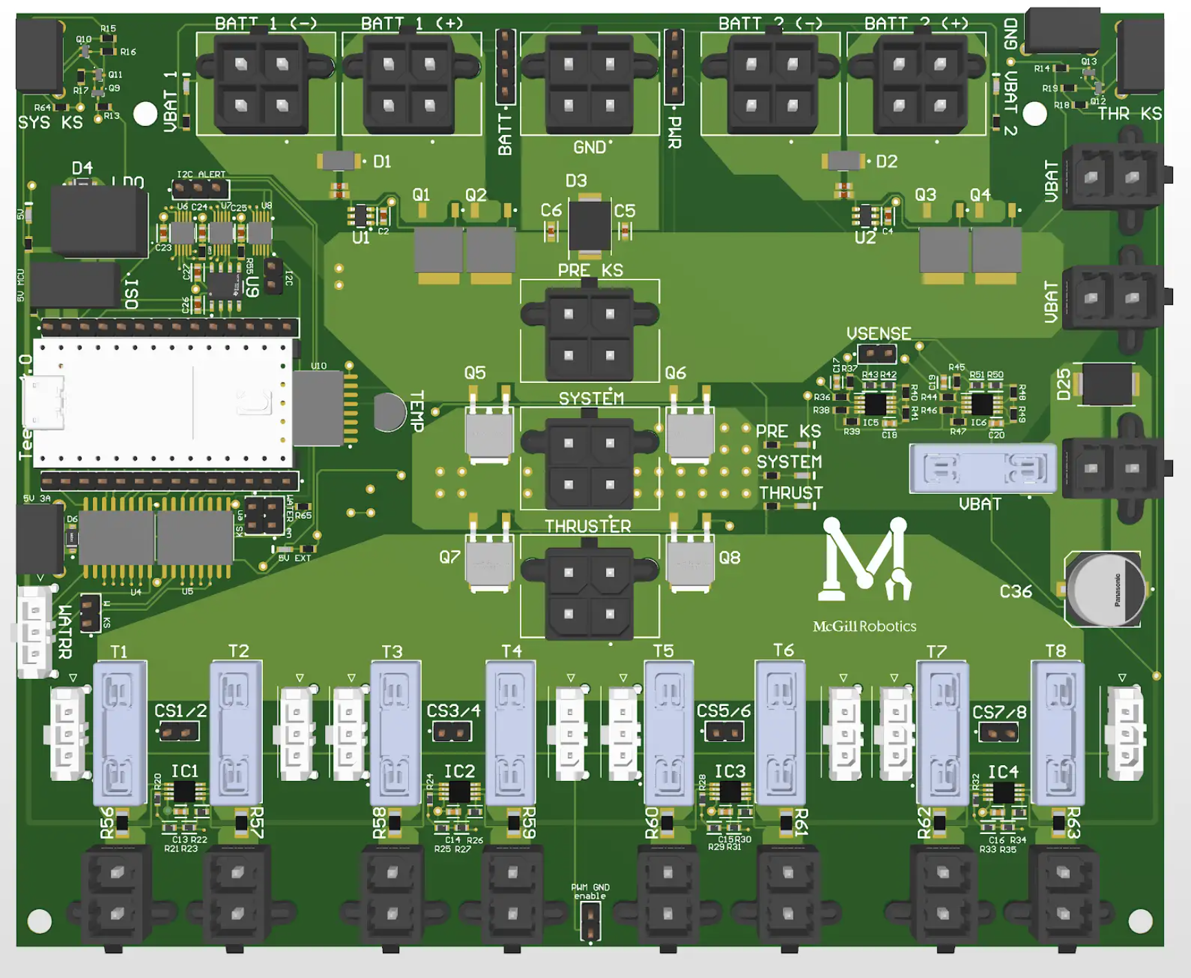
POWER BOARD
The Power Board manages the AUV's power distribution, thruster control, and kill switches.
It features voltage regulators, a Teensy 4.0 microcontroller, a dual battery input hot-swap controller, battery voltage sensors, thruster current sensors, water leak detection circuitry, and a two-stage kill switch system. The main kill switch cuts power to the thrusters, while the secondary switch can shut down the entire system in emergencies. The high voltage and low voltage nets are fully galvanically isolated to prevent any ESD spikes or current surges from affecting the integrity of the microcontroller’s power. In case of a leak, the microcontroller can also automatically kill the system. LEDs indicate powered nets and the active battery. The eight thrusters have 15A reset fuses to limit current draw. Dual-battery support allows for mismatched voltages, discharging the more charged battery first until balanced. The AUV can operate fully on a single battery, with a second battery extending mission duration. Current and voltage data are relayed through ROS to the Jetson and other embedded systems.

DISPLAY BOARD
The Display Board, featuring an ILI9341 display controlled by a Teensy 4.0, facilitates critical information monitoring for the AUV.
The screen and Teensy communicate via the Serial Peripheral Interface (SPI) protocol. The external pressure sensor connected to the Display Board determines the AUV's depth and publishes this information to the Jetson using ROS. The board subscribes to multiple ROS topics to display crucial data, including battery voltages, depth, and the status of each thruster, DVL, IMU, cameras, and other boards. It enables visualization of subsystem status and battery discharge, and is positioned under the top side circular window for easy inspection.

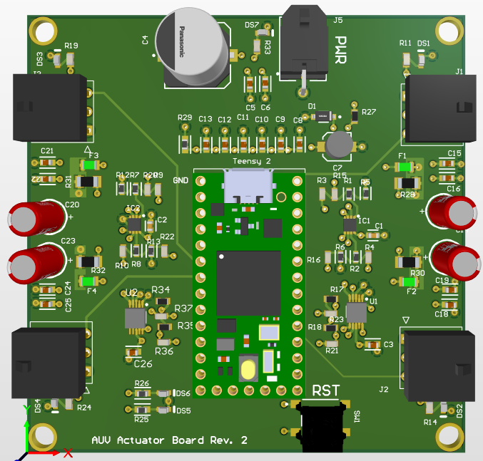
ACTUATOR BOARD
The actuator board is implemented to control and automate a torpedo launcher and a grabber. This PCB, which is powered up by a 5V BEC converter, can control 4 servos using its onboard MCU. The power input for the teensy first passes through an LDO to ensure a consistent input voltage. Each servo connection has a resettable fuse, status LED, and capacitor unit. The capacitor unit includes bulk and bypass capacitance to ensure a stable supply voltage. Additionally, the board has current sensing ICs connected to the Teensy via an ADC to detect when the servo has reached stall current (when object is held for grabber). The board also has access points to allow communication protocol changes and the fabrication of additional testing components.
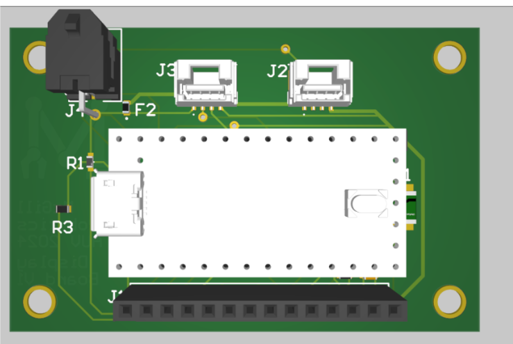
PERIPHERALS BOARD
The peripherals board ensures reliable communication between the doppler velocity logger (DVL) and outside devices. Wired communication is established through the built-in micro-usb port that utilizes a FTDI USB-UART converter to communicate with the DVL. Furthermore, Ethernet communication is also possible through the Ethernet connector. On the DVL side, all wiring goes through a 8 pin connector that routes every input and output to their designated location. The DVL is powered by a separate power line accessible through a two pin Mega-fit connector. The line is equipped with a diode for reverse polarity protection, Schottky diode for clamping, and capacitors for filtering.
The PCB also includes a reed switch accessible through the two pin micro-fit connector that is used for the thruster kill switch.These independent subsystems are implemented together due to their physical proximity on the robot; this allows for a much stronger anchoring of the reed switch over the magnetic plug.

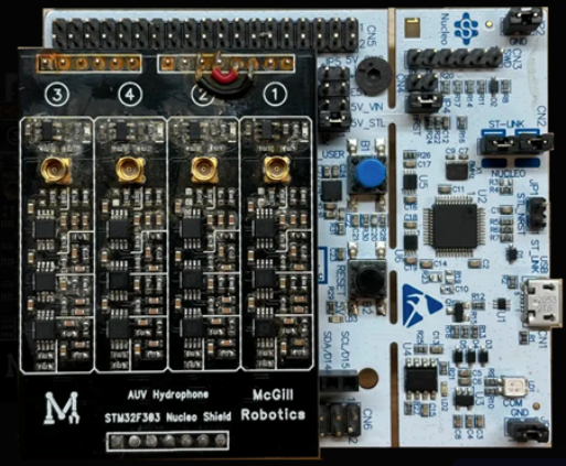
HYDROPHONE BOARD
The hydrophone board consists of an STM32 Nucleo connected to a custom-designed signal shield. The shield is an 8th order Butterworth filter that isolates the pinger frequency and filters out noise from thrusters and servos as well as other EMI.