
Development of a
Suspension Mechanism
Project Description
Introduction
Every year, the McGill Robotics Design Team designs a Rover with the goal of participating in student competitions, specifically the Canadian International Rover Competition (CIRC) and the University Rover Challenge (URC). For the past four years, the Team has designed its rover according to the CIRC requirements. Having the intention of attending URC next year, the team needs to adapt its rover to this competition’s stricter constraints. Although both competitions have similar objectives regarding navigation of hilly terrain similar to that found on Mars, URC imposes stricter size and obstacle clearance requirements.
The previous double wishbone suspension design worked well for stability and shock absorption in the context of CIRC; however, it is inadequate for the large obstacles found at URC and does not satisfy the size requirements. As a result, McGill Robotics has decided that this year they would like a complete redesign of their suspension to better fit the needs of the competitions.


Project Description
Problem Definition
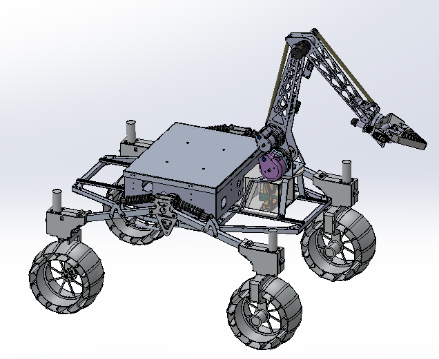
The objective of this project is to provide a new suspension design for the team that will enable the rover to overcome obstacles up to 30 cm efficiently while also cutting back on weight. The design needs to fix the main issues encountered with the previous design, which can be seen in Figure 1. For example, the double wishbone suspension design required four points of contact with the frame of the rover per linkage, which restricted space within the frame subsystem and access to the inside of the rover. To meet the Client’s needs, the proposed design will need to fulfill the competition’s tasks while remaining within URC’s strict size constraints.
Analysis
Simulations and Load testing
After selecting the final conceptual design, the design process was conducted through several steps to identify the required parts and optimize their geometries. Most of the dimensional constraints were initially fixed by the client, such as the distance between the wheels and the frame, the width of the frame or the vertical distance above each wheel reserved for the steering mechanism. This was useful to model the rover in a MatLab simulation, and calculate the maximum loads applied to different components through several iterations. The results of the simulations helped design the shock absorption system and select the best linkages geometry. Calculations of the loads transferred to the various components are detailed in their respective sub-sections, as well as the finite element analysis iterations conducted to refine the design.


Results
Final Concept Assembly
Overall, the conception process consisted of several steps that led to the final design. First, hand calculations were performed to determine the forces and moments on each of the suspension components. Once those were determined for three different scenarios, CADs of each mechanical piece were modeled, and iterations between Finite Element Analysis and topological optimization were carried out to refine the design. Those steps allowed material and weight savings. In the end, the team obtained a system that fulfills its tasks and that fits in the predicted budget and weight targets.
