Mechanical Subsystem
2026 Mechanical Team
Nadim Asmar, Kayra Gedik, Aurelia Stearns, Tian Hui Wang, Vincenzo Bigattini, Typhaine Braucourt, Kai-Hsin Chen, Luca Dimora, Matthew Kirkbride, Stuart Klenner, Alicia Lista Rosabal, Frank Wu, Didier Zhang
Hull
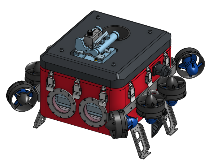
The hull is rectangular, with a large opening on the top, allowing easy access to the internal electrical systems. This is a change from this AUV’s predecessor, Clarke, which had a cylindrical hull with tightly-layered electronics shelves that were difficult to access. The hull has windows on the front and bottom for cameras, and a window on the top to view an electronic board that displays the AUV’s system status. The hull is constructed from Aluminum 6061 and protected with an anodized coating. This material was selected primarily for its high thermal conductivity, which allows the hull to act as a passive heat sink for internal electronics, reducing the need for active cooling. The anodized surface provides corrosion resistance, essential for long-term underwater use, and has the added benefit of being non-conductive, which helps prevent unwanted electrical grounding through the structure.
The main body of the hull has a wall thickness of 1.5 cm, while the lid is slightly thinner at 1.0 cm. The thicker hull allows the addition of non-through threaded holes without compromising structural integrity, and also contributes to making the hull itself approximately 5% positively buoyant. To enable modular assembly and easy integration with other subsystems, the hull includes threaded holes that do not penetrate fully through the wall. These are used to mount the latches, thrusters, chassis supports, and actuators.

Buoyancy
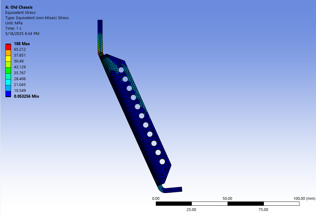
To decrease the distance between the center of mass and the center of buoyancy, the overall weight of the hull and chassis was reduced and the buoyancy foam was spread more evenly across the hull. To reduce the overall weight, the hull lid was modified, the internals were adjusted and the chassis leg structure was optimized. The chassis structure was optimized using finite element analysis to evaluate stress concentrations, and designed the leg to compensate using the least amount of material. The inner part of the hull lid was machined to be thinner to reduce weight as well. These changes have reduced Douglas’s weight by roughly 1 kilogram, so the actuators can be incorporated with only a small increase in our overall weight.
The buoyancy foam was designed to ensure the AUV meets the requirement of being approximately 5% positively buoyant, as specified by competition rules. The foam layout is also positioned so that the center of buoyancy remains slightly above the center of gravity, which improves stability and maneuverability.
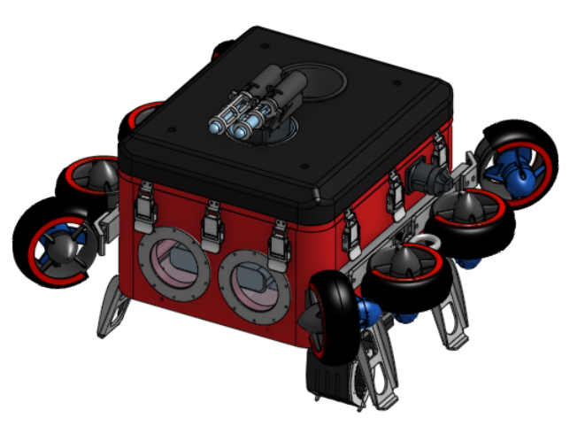
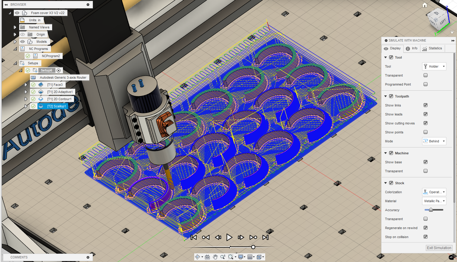
The foam components were added in two locations: over the thrusters and on top of the hull. The foam covers for the thrusters also provide a layer of physical protection for the thrusters, shielding them from impact damage during transport, handling or regular usage. The total volume of the top-mounted buoyancy foam was reduced compared to the previous year’s design. The new volume represents 50% of last year’s foam volume. The adjustment was made to decrease the upward buoyant force and reduce the offset between the center of buoyancy and center of gravity.
All buoyancy foam components were manufactured in-house using extruded polystyrene (XPS) foam. This material was selected for its low density, ease of machining, and durability in underwater environments. After machining, the foam was first coated with a layer of liquid rubber to provide water resistance, followed by an outer layer of epoxy resin for rigidity. This coating process is designed to extend the operational life of the foam by preventing water absorption and surface damage.
Waterproofing and Sealing
The hull features two front-facing windows for the main cameras, one downward-facing window, and a top-facing window embedded in the lid for a display screen. All of these windows are circular, with the front and bottom windows each measuring 72 mm in diameter, and the display window measuring 90 mm.
In addition to the windows, the hull contains several electrical connection points. Each side of the hull includes three 8-pin Subconn connectors, while the rear has three 6-pin Subconn connectors, totaling nine waterproof connectors. The bottom of the hull contains additional openings for a depth sensor and hydrophones. All these features are potential points of leakage and are therefore sealed primarily using o-rings, with the depth sensor being the exception.
The o-rings used in sealing the windows and connector glands are made of nitrile rubber. The o-ring for the hull lid is a custom component due to the irregular geometry of the sealing surface. It was manufactured in-house using nitrile cord stock. The depth sensor and cables that have been soldered together use marine grade epoxy for sealing.
Maintenance of the lid o-ring is especially important, as it is more exposed than other seals and is frequently handled. The o-ring should be inspected for cracks or deformation every time it is used and stored in a sealed plastic bag between each use. When the hull needs to be sealed for a pool test, the o-ring should be removed from the plastic bag using latex gloves. Before applying the o-ring grease, the o-ring groove and the o-ring itself should be cleaned and placed in the groove carefully right before sealing the lid, and avoiding any twisting or kinks. When closing the latches, follow the latching order below to apply an even pressure to the seal.


Design Verification
Our testing process focused on ensuring the hull's durability and seal integrity under simulated pressure conditions.
Finite element analysis verified that the hull could withstand 30m depth with a safety factor of two. The weight and buoyancy were consistently monitored to maintain the AUV’s center of mass near the hull's center. Dry ice was used to simulate two atmospheres of water pressure with carbon dioxide gas to test the hull's seal quality. The ideal gas law calculated the required dry ice, and pressure was monitored to detect leaks. The test showed that the early version of the hull was not completely sealed under two atmospheres of pressure.
Internals
The electronics were secured within the hull using a combination of acrylic and 3D-printed mounts. Each mount underwent multiple design iterations to achieve optimal security, accessibility, and thermal management. The bottom mounting plates and the electronic stack were precision laser-cut from clear acrylic, enhancing visibility for both electronic monitoring and leak inspection. The batteries were encased in a custom 3D-printed mount and secured with rubber bands, allowing for necessary ventilation. Final positioning of electronic components was strategically planned alongside the electrical team, prioritizing accessibility and optimal weight distribution.

Thruster positioning
The thruster positioning configuration was selected by comparing various potential setups involving different distances, angles, and placements. To determine the optimal configuration, an algorithm and simulations were used to compare the thrust required for various maneuvers. As a result, the most energy efficient configuration was implemented in the robot as shown in the image on the left.
To secure the thrusters in their optimal positions, custom mounts were designed and machined. After multiple design iterations, prototyping, and calculations, the final version of the thruster mounts were CNC milled to achieve the desirable strength and precision.

Chassis
The team designed a minimalistic yet functional chassis for effective task actuator support.
The chosen material, Aluminum 6061, offers suitable structural and chemical properties for marine applications, allowing for slender designs and improved hydrodynamics. The chassis is attached with screws for easy transportation and future modifications. Structural integrity is validated through finite element analysis of inertial forces. Task mechanisms are placed below the hull to stay within the camera's view, avoid thruster wash, and lower the center of mass below the center of buoyancy. Buoyancy is adjusted to +5% using a custom hydrodynamic polyurethane foam topper, with fine-tuning done through additional components. The center of mass is balanced with small weights on guide rails, allowing quick, tool-free adjustments. This fine-tuning reduces thruster workload, enhancing maneuverability.


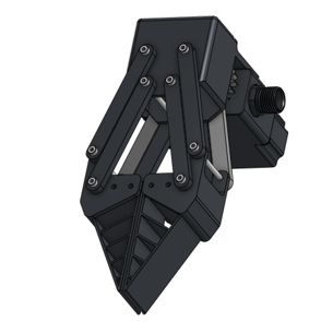
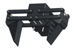
Grabber
The grabber subsystem was designed to retrieve and sort objects placed on a pool-bottom table, a key component of the 2026 RoboSub object manipulation task. This year’s design was focused on being able to grab multiple different shaped objects without relying on interlocking fingers.
The flat sided edges with the hollow inner claw allows the face to deform slightly, to allow it to pick up objects regardless of their orientation or shape. They were 3D printed out of TPU which allows them to be more flexible and long-lasting.
For software-assisted object recognition, the claw was repositioned from the AUV’s rear to directly beneath the downward-facing camera. The mount offsets the claw by 2.5 inches using a 3D-printed rail and two C-brackets. This dimension is optimized to maximize reach: when the grabber is closed, it extends as far as possible; when opened, it remains within the chassis profile. This design allows the AUV to rest on hard surfaces without risking damage to the grabber if it's left attached. It also minimizes the need for the AUV to approach the underwater table closely when picking up objects, reducing the risk of collision. T-nuts allow for precise lateral adjustment along the rail to optimize camera alignment.
We also plan for the grabber to used for the dropper tasks, as the grabber and hold and release objects we design to be droppers, making the claw multifunctional.
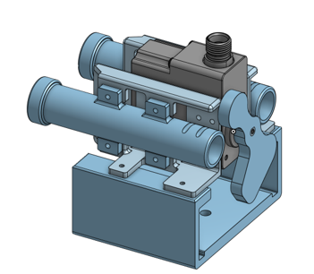
Torpedo
This year marked the first integration of a torpedo launching system into our AUV. The launcher is a spring-powered system designed to meet RoboSub’s 2.0” x 2.0” x 6.0” size and 2.0 lb weight constraints, with the current torpedo measuring 14.00 mm in diameter and 80.00 mm in length. Our final torpedo design complies with these constraints, allowing the vehicle to carry and deploy up to two torpedoes per run.
The torpedo actuator system was drastically improved from last year’s design both in terms of reliability and ease of use. A major wall the mechanical team ran into was ease of reloading with breaking the outer-casing.
The new design is based on a pneumatic model, but with hand-loaded springs instead, where the tail-end of the torpedo can be used to help load the mechanism. This year the servo motor rotates a “door” covering the torpedoes allowing them to launch as they are released one by one. The mounting is similar to the previous year but is less modular.
Similarly, the torpedoes themselves were improved, using a helical design to maximise hydrodynamic efficiency and were 3D printed to be neutrally buoyant.
The spring used in the system changed after different tests were conducted. Adjustments were made to the spring stiffness, internal alignment, and exit velocity. Additional tests focused on identifying the torpedo’s launch angle deviation so that software could apply angle corrections during autonomous targeting.